
PERSONAL EXPERIENCE REPORT
Build Your Own Fish Finder Battery: Gerd's 12.8 V, 15 Ah Power Box
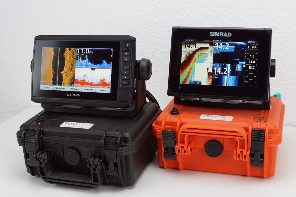
Finally Enough Power for the Fish Finder - A 12.8V/15Ah Power Box
Fish finders and combination units are designed for permanent installation. Since I frequently use rental boats and like to bring my own equipment, I looked extensively into possible portable solutions. The products offered by specialist retailers were not what I was looking for. The power supply was often inadequate for power-hungry modern fish finders, and the quality of the individual components in the packages was not worth the asking price. So I developed my own plan to build a suitable power box for my fish finder. I would now like to describe in more detail how it developed and the benefits this solution provided me.
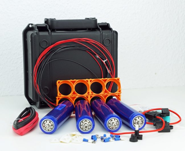
This do-it-yourself kit is
- ideally equipped with 15Ah to power modern, high-demand devices,
- saves about 50% of the usual weight by using application-safe LiFePo4 battery cells,
- is convenient to operate
- and is also water-resistant
in its design. In practice, the stored energy lasts for several days. It is no comparison to the usual complete packages from accessory suppliers, which tend to be minimally equipped. However, that also applies to the costs involved. This approach, as presented here, could not be implemented for free, although the higher expense pays off in the long run. The service life of a LiFePO4 fish finder battery, its energy efficiency and its low weight alone were worth the extra cost to me.
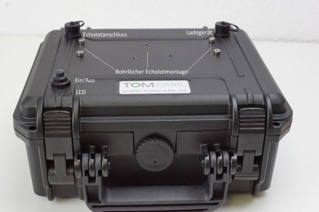
The centerpiece of the kit is a TOMcase outdoor case (XT 235H105), which is made for rugged outdoor use and is therefore not only rigid and stable but also waterproof. Its dimensions are exactly right to fit in the standard universal bag from Think Big or comparable suppliers—only its overall height is slightly greater. For the power supply, I used a LiFePo4 battery kit consisting of four Headway lithium iron phosphate cells (LiFePo 40152 or 40160), 12.8V/15AH. I installed these in the case together with a battery management system (BMS) and a balance lead for cell monitoring (digital display with beeper).
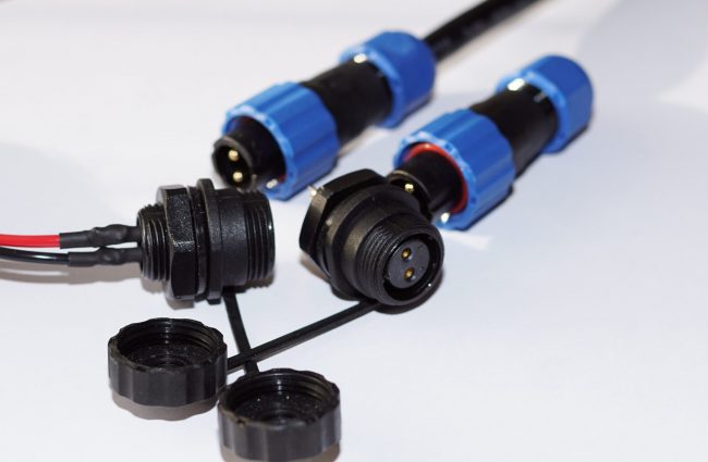
On top of the case,
- two waterproof sockets (fish finder connection and charging socket),
- an on/off switch for physically disconnecting the fish finder's power supply,
- and an LED as a power indicator
provide the connections to the outside world. All components are water-resistant. This solution also allows the power case to be used outside the fish finder bag setup, such as when the fish finder is mounted on the railing or 12V power is needed elsewhere.
All the components used for this project were available from specialist retailers or various online marketplaces. I have summarized them again in the list below.
My wiring diagram for the project was as follows:
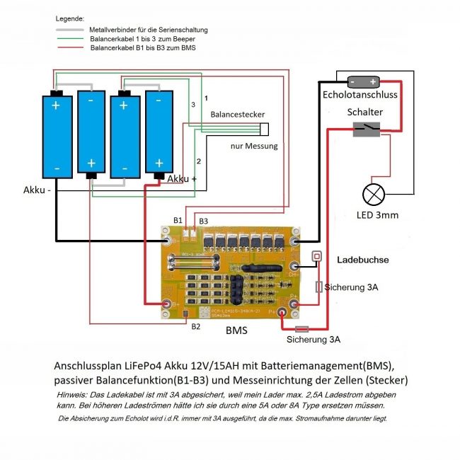
Do It Yourself—How to Assemble Your Own Fish Finder Battery:
In the following sections, I will show you step by step how I assembled my DIY fish finder battery. And how you could do the same.
Step 1—Purchasing the Components:
First, I obtained all the components and equipment. The charger, for example, was used very early on to fully charge and balance the individual cells so that each cell would later reach full capacity in the battery pack.
I did this soon after purchase so that any complaints could still be submitted within the two-week return period.
Step 2—Installing the Sockets, Switches and LEDs in the Case:
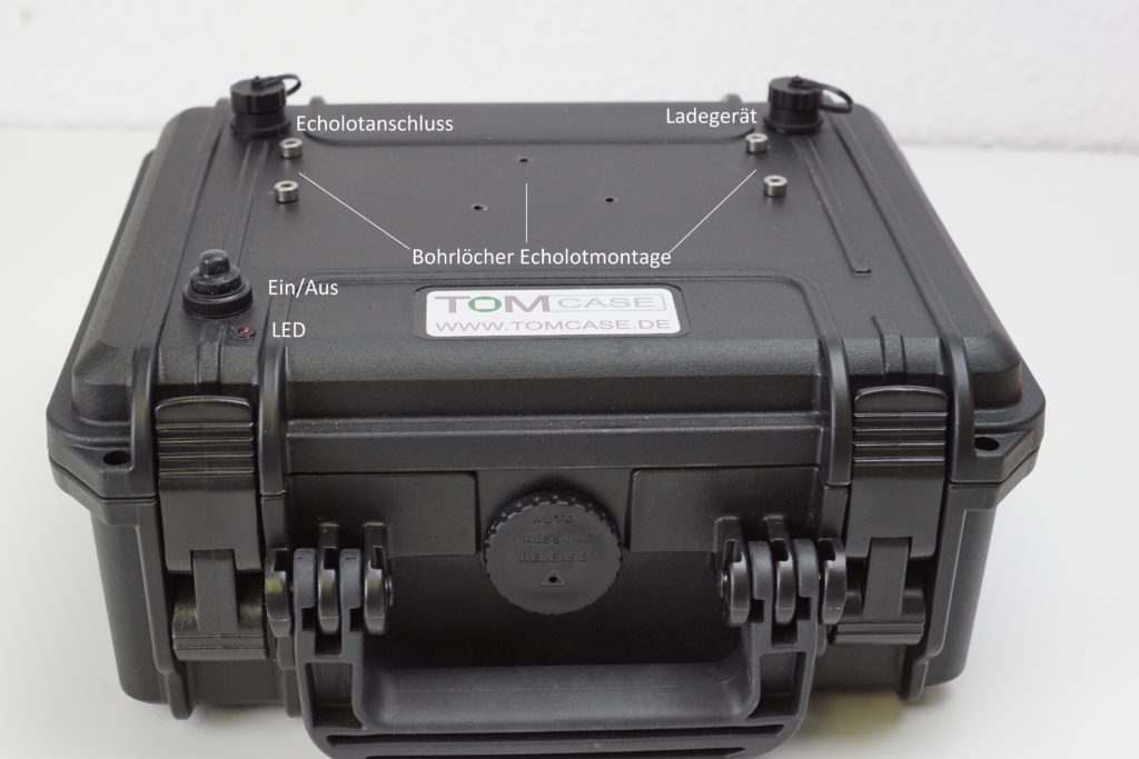
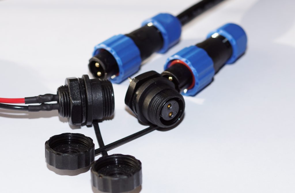
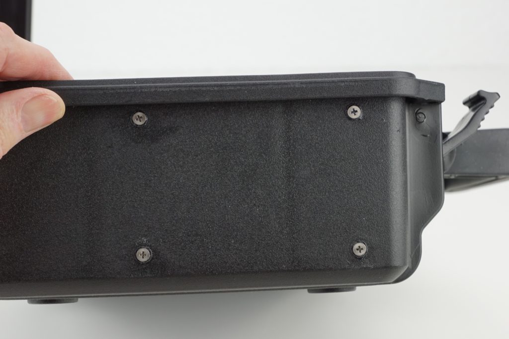
As the first step, I drilled the required holes for the sockets, switches and LEDs in the case. The BMS circuit board was mounted on four standoffs against the inside left wall. This required four holes for the M3/16mm mounting screws.
Step 3—Soldering the Circuit Board:
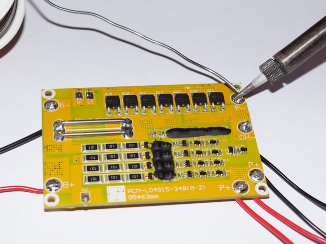
In the next step, I soldered all the cables to the BMS circuit board. A 2.5mm² automotive wire was connected to terminals B+/B-, while the prefabricated leads with inline fuses were connected to P+/P-. The two wires for the charging socket were 1.5mm² (max. charging current 5A). Finally, the three connecting wires (0.5mm²) for balance connections B1-B3 had to be attached.
The required cable lengths were generously sized so that all connections could later be made without tension. When soldering, it made sense to position the individual cables so that they ran in exactly the direction—downward—in which they would later be routed. This avoided unnecessary cable loops and strain on the solder joints.
Step 4—Installing the First Components
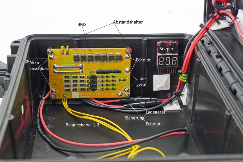
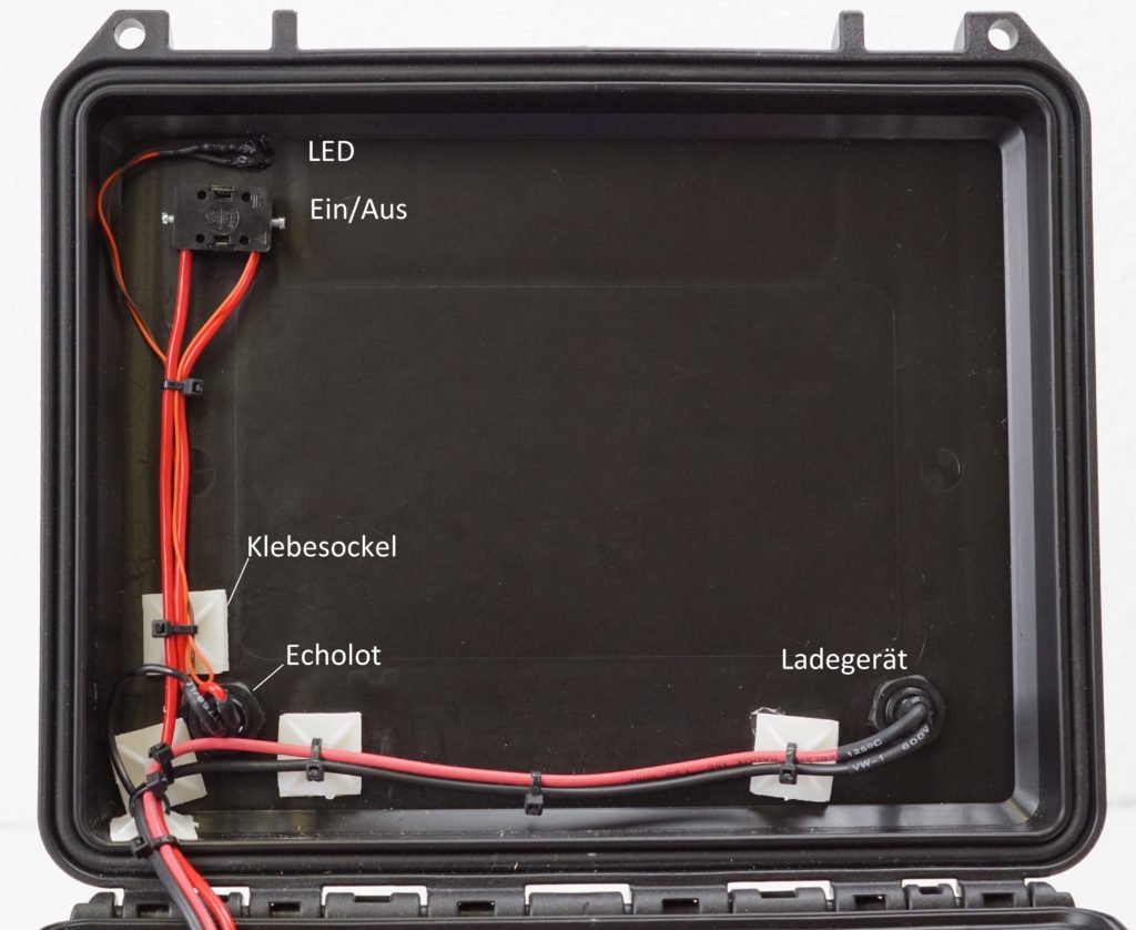
The two sockets, the on/off switch, the LED and the machine screws with standoffs for the BMS circuit board were now installed. The machine-screw holes, LED and ON/OFF switch—from below only—were sealed with Sikaflex to make the openings watertight. All the other components already had appropriate sealing rings, but a little additional Sikaflex does no harm here either.
Next, the BMS circuit board and cables were placed in the housing and secured. The cables were then routed step by step to the designated locations (see illustration) and fastened with cable ties to the previously installed adhesive mounts. I then shortened the individual wires to the required length. The cable ends were now screwed or soldered to the fish finder socket and charging socket (depending on the sockets; see component list), after which the remaining connections to the designated components were made.
Step 5—The Battery Pack:
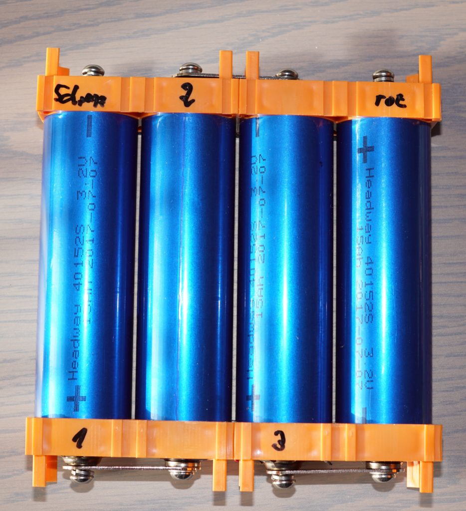
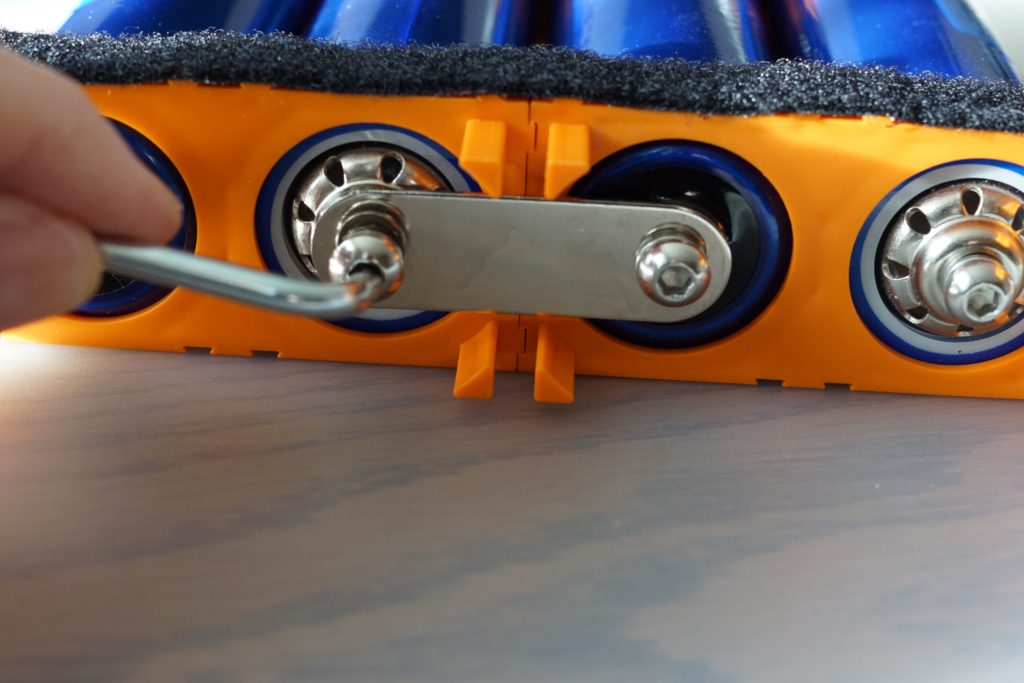
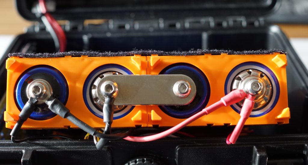
Next came the battery pack:
- The individual cells had already been fully charged to 3.6V,
- the plastic holders were assembled,
- and the cells were inserted into the holders exactly according to the diagram (see illustration).
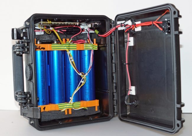
The cells were then fitted with their metal connectors (series connection), as shown in the wiring diagram. During assembly, all unused terminals were temporarily covered with electrical tape to prevent short circuits. After preassembly, appropriately cut double-sided hook-and-loop strips with adhesive backing were attached to the plastic holders, but the battery pack was not yet attached to its intended location in the housing (see illustration).
Step 6—Wiring:
Next came the additional balance cable for monitoring the individual cells. A beeper is connected to this cable to monitor cell voltage and emit an audible signal (beep) when it falls below the threshold. The beeper was programmed for a voltage of 3V, so that an alarm is triggered at that point during actual operation.
Ring terminals were attached to the loose ends of the individual cables so they could be mounted at the battery-cell positions shown in the illustration.
The green leads (see diagram) connect to the same positive terminals as the BMS balance leads (B1, B2, B3), so both were combined in one ring terminal. The remaining connections could now be made according to the wiring diagram. Finally, battery+ and battery- were connected. The battery pack was then attached to the designated location on the bottom of the housing (remove the protective strips from the double-sided hook-and-loop tape first).
Important: First, I connected the charger to activate the BMS. The required plug had already been attached. The cells' state of charge could now be read on the beeper's display. Thanks to precharging, they were at approximately the same level.
For the test with a fish finder, a Simrad Go7 was mounted on the case and connected to the power supply. During the subsequent simulation run, the unit displayed an initial voltage of 13.3V—the expected result. I then completed a full simulation run with the unit at 100% screen brightness. The measured power consumption was 0.65Ah. After 17.5h, around 25% capacity remained. The battery was therefore 75% discharged, a respectable result for the first use.
The battery manufacturer promises about 2000 charging cycles when the battery is regularly discharged by no more than 80% of its total capacity, so after this initial discharge cycle, a 7-inch fish finder can be expected to provide around 18h of operating time. With a 9-inch model and average power consumption of 0.9Ah, the calculated operating time would be around 13h. In both cases, this is at full screen brightness and using only 80% of the capacity.
In summary, for my project I placed particular importance on:
- Buying selected or tested cells.
- Using a perfectly matched charger for LiFePo4 batteries.
- Fully charging each cell individually before assembly (the retailer could also have done this).
- Eliminating potential hazards (such as short circuits) during assembly.
- Following all safety-related instructions.
Incidentally: My complete equipment for fish finder fishing, including the carrying bag, 12.8V / 15Ah power box and a 7-inch Garmin Echomap Plus 72sv combination unit, weighs only around 5kg in total.That is about as much as a 15Ah lead-acid battery (4.5kg) weighs on its own.
Important Notice
All electrical work and installations should be carried out only by qualified individuals with the necessary technical knowledge. 12V batteries and rechargeable batteries are not toys. If handled incorrectly, they pose a serious risk of severe personal injury and property damage.
Disclaimer
This article merely describes a project I completed to build a battery-powered fish finder power supply for my personal needs. It is not an assembly guide for this or any similar project and must not be understood as such. Because my own safety is very important to me, I carried out this project with due care and to the best of my knowledge—and tested it in practice.
I accept no liability or warranty for the soundness of the planning, construction or operational safety of the finished product. Anyone using my description to replicate a similar project does so at their own risk. I accept no liability arising from following my plan.
My Component List
(Amazon= 1 / Litrade.de= 2/ electrical retailer= 3/
| Quantity | Description | Example Supplier |
| 1 | TOMcase XT 235H105 outdoor case | 1 |
| 4 | Headway LiFePo4 cells 12.8V/15AH 40152/40160 | 2 |
| 3 | Metal connectors for series connection | 2 |
| 4 | Plastic holder for Headway 15AH cells | 2 |
| 1 | BMS circuit board 4s 15AH | 2 |
| 1 | 5-wire balance cable with plug | 2 |
| 2 | Automotive mini fuse holder with 1.5mm² cable | 1 |
| 8 | Stainless steel machine screws M3/16mm with nuts | 1 |
| 4 | Cylindrical plastic standoffs for M4 | 1 |
| 0.5m | Red automotive cable 2.5mm² | 1 |
| 0.5m | Black automotive cable 2.5mm² | 1 |
| 1m | Red automotive cable 1.5mm² | 1 |
| 1m | Black automotive cable 1.5mm² | 1 |
| 1m | Yellow automotive cable 0.5mm² | 1 |
| 15 | Cable ties 150mm/2 white | 1 |
| 15 | Adhesive mounts 19x19mm white | 1 |
| 1 | On/off panel-mount pushbutton switch 6A or more Waterproof | 1 |
| 1 | Waterproof cover for pushbutton switch | X |
| 1 | 3mm red diffused LED, 12V, with cable and mounting bezel | 1 |
| 2 | 12mm waterproof panel-mount sockets* | AliExpress or eBay |
| 2 | 12mm waterproof plugs* | AliExpress or eBay |
| 1 | 3mm heat-shrink tubing for solder joints | 1 |
| 8 | Blue M6 ring terminals | 1 |
| 1 | Think Big black fish finder bag | 1 |
| 1 | Imax B6AC V2 charger (original!) | 1 |
| 1 | 1.5mm lead solder | 1 |
| 1 | Sikaflex 221i sealant 300ml | 1 |
That brings us to the end of my experience report on "Building Your Own Fish Finder Battery!" If you have any questions, additions or comments, start typing: I look forward to your feedback! Or take a look at our detailed fish finder test, which includes the best-known fish finder models from all major manufacturers, such as Garmin, Raymarine and Lowrance.